The thermal stability of the brake system determines the constantness of the braking performance. The overheated braking system will result in significant thermal decay, reduced braking friction coefficient, and longer braking distance. Due to the increase in vehicle weight and maximum speed, higher requirements are placed on the thermal stability of the brake system. At present, most domestic institutions only use the existing theoretical knowledge to analyze the heat dissipation performance of the brakes, and there are few studies to judge the heat dissipation capability of the brakes from the actual situation. A company in China plans to produce a brake disc with two production schemes: straight air duct and curved air duct brake disc. In this paper, the influence of the brake disc structure on the heat dissipation capability of the brake during the actual braking process is studied by using modern software engineering technology. The results show that the curved air passage brake has better heat dissipation performance and dynamic characteristics, which provides a reasonable production plan for the enterprise. reference.
Brake disc thermal design
When braking, the kinetic energy of the vehicle is converted into heat, which is transmitted to the brake disc, the brake or convected into the air. The heat of the whole system is adjusted by the brake disc. The large and heavy brake disc has a large heat capacity, which can well receive the frictional heat generated during braking, and avoid the thermal attenuation effect of the friction block due to overheating of the system. The material and structure of the brake disc are applied to the entire brake. The temperature of the system has a large effect. During the braking process, the frictional heat energy is absorbed and stored by the brake disc on the one hand, and on the other hand, as the temperature rises, the heat is dissipated through the convection and surface radiation of the adjacent parts of the brake disc, the surface and the air passage. The result of the balance of thermal energy inflow and outflow is an increase in temperature and subsequent cooling of the brake disc brake.
The temperature of the brake disc rises rapidly during a single braking. The high temperature value depends on the energy and quality of the vehicle at the time, and on the other hand, the heat storage capacity and quality of the brake disc. During the cooling period after braking, the convection and heat radiation of the brake disc through the air passage plays an important role in the temperature. In order to improve the cooling performance, especially for high-power vehicles, a brake flow around the structure is employed. The outside cold air is guided to the brake disc through the air passage and the flow guiding element, and then blown out by the wheel through the brake disc, thereby improving the cooling speed of the brake disc.
Ventilation structure design
The brake disc to be produced has a diameter of 260 mm and a thickness of 24 mm. The linear air duct type cooling fins are evenly distributed along the center of the brake disc, and there are 37 cooling fins. The cooling fin width is 5mm, the length is 39mm, and there are seven ventilation holes. The brake air passage structure is shown in Fig. 1.
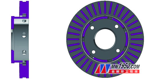
Figure 1 Cross-sectional view of the brake disc of the linear air duct
The curve air duct brake disc has the same parameters as the linear air duct brake disc except the cooling fin, and the braking performance is basically the same. In order to facilitate the manufacture and research, the curved air passages are designed as regular circular arc blades. The arc shape is shown in Fig. 2. Among them, βb1 and βb2 are the air inlet inlet angle and the blade outlet angle respectively, and δ1 and δ2 are respectively Ventilation height and fin thickness. From the shape of the cooling fin, the flow path to the rear air passage (βb2 < 90°) is smoother, the resistance is small when the airflow flows therein, and the energy loss is small, so that the backward cooling fin is selected. After the basic shape of the air passage is determined, a reasonable air passage entrance angle βb1, an exit angle βb2, and a blade number B are calculated. In order to meet the requirements of two-way heat dissipation performance, βb1=90° is generally adopted, and the cross-sectional area S1 of the air inlet of the air duct should be larger than the cross-sectional area S2 of the air outlet, wherein the outer diameter of the brake disc is 260 mm, and the inner diameter of the friction ring is 160 mm, which is calculated. , βb2 ≤ arcsin (160 / 260) ≈ 38 °.
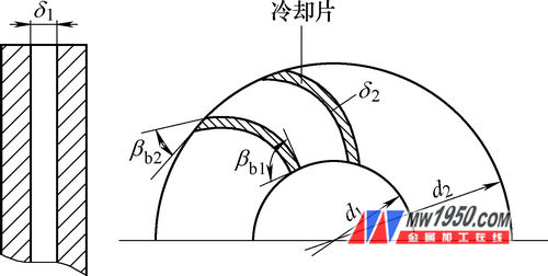
Figure 2 Schematic diagram of curve ventilation channel calculation
According to the above analysis, the angle of the exit angle and the number of air ducts are the main parameters for optimizing the air passage of the brake disc. The man-machine interactive iterative method is adopted to calculate the angles of different exit angles. After repeated iterations and improvements, the relevant parameters of the curved air passages in the air passage of the brake disc are determined as the inlet angle of 90° and the exit angle of 30. °, in order to have a more reasonable comparison with the linear ventilated brake disc, the number and width of the cooling fins are the same, that is, there are 36 air ducts with a width of 5 mm.
Establishment of finite element model for numerical simulation of brake flow field
1. Simplified model building
During the braking process, the brake has both the rotation around the central axis and the forward speed, and the air flow is turbulent. Therefore, the most widely used standard k-ε model is selected to deal with such turbulence problems, and the conservation of mass and conservation of momentum The equation yields a governing equation and will not be described in detail here. In theory, the study of the ventilation and cooling capacity of the brake disc should consider the effects of the axle and the wheel, the suspension system, and the steering system in the vehicle system, especially the air flow in the vehicle bottom and the fender. According to the theoretical research modeling, the whole vehicle model should be established, and the calculation workload is large, which takes time and manpower. This paper studies the comparative analysis of the heat dissipation performance of the linear air duct brake disc and the curved air duct brake disc under the same external conditions. The actual modeling does not consider the influence of the vehicle system, and the model is simplified as the air around the brake disc. The flow field model, which reduces the amount of computation is effective and feasible.
The brake disc rotates at a certain angular speed during deceleration until it stops, and the surrounding air rotates accordingly, creating a rotating air field about 5 mm around the outer surface of the brake disc, simulating the rotating air flow on the surface of the brake disc and the airflow in the near wall area of ​​the brake disc. Layer; in the absence of wind, the cold air far from the brake disc can be regarded as static, creating a static air field; the brake disc dissipates its own heat into the surrounding air flow field, and according to its material characteristics, it is used as a solid domain. Numerical Simulation. After the three main models are built, they are integrated into the ANSYS/CFX pre-processing and assembled into one, as shown in Figure 3.
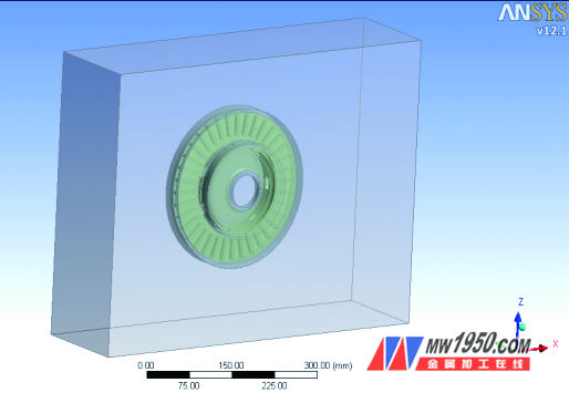
Figure 3 Total model structure in CFX
2. Meshing and load boundary conditions
The model consists mainly of three parts: the still air domain, the rotating air domain and the brake disc. Among them, the static air domain and the rotating air domain are both fluid domains, and the brake disc is a solid domain. Both the still air and the rotating air domain are treated with tetrahedral mesh elements and the mesh at the interface between the rotating and stationary domains is refined. After the brake disc is divided by the tetrahedral mesh unit, the friction surface of the brake disc is mesh refined and encrypted. After the division is completed, the number of meshes and grid quality of each domain tetrahedral unit are shown in Table 1.
Table 1 Model grid quantity and quality list

The system includes three boundary conditions: inlet boundary conditions, exit boundary conditions, and wall boundary conditions. The flow rate is given at the fluid inlet to simulate the running speed of the vehicle; the fluid outlet pressure is zero relative to the atmospheric pressure, which is convenient for observing the flow of the fluid around the brake; the wall surface is subjected to temperature, heat flow and convective heat transfer boundary conditions. The car is braked at an initial speed of 120km/h. The initial velocity of the inlet boundary is 33m/s, the outlet boundary pressure is 0Pa, the wall temperature is 22°C, the vehicle brake deceleration is 5.76m/s2, and the entrance boundary of the static air field is The instantaneous value of the speed from the start to the end of braking is (33-5.76t) m/s.
Numerical simulation results and analysis
1. Comparison and analysis of ventilation performance
Numerical simulation of the air flow field around the brake disc provides a map of the air temperature and velocity around the brake disc and in the air duct at different braking times. The maximum temperature values ​​of the brake disc at a certain time before and after improvement are shown in Table 2. Taking the 2s after the start of braking as an example, the air temperature and velocity distribution around the brake disc and the air passage are given, as shown in Figure 4 and Figure 5, respectively.
Table 2 The highest instantaneous temperature at different times
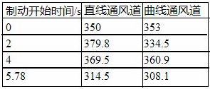
Figure 4 temperature distribution map

(a) straight air duct

(b) Curved air duct
Figure 5 speed distribution map

(a) straight air duct
 Curved air duct")
(b) Curved air duct
The comparison of the results shows that under the same test conditions, the temperature of the air around the brake disc of the linear air duct changes momentarily during the braking process, but the highest temperature is always near the surface of the brake disc and is distributed inside the brake disc away from the air inlet. The airflow in one side is close to the ground; the distribution of velocity in the flow field does not change greatly with time, and the velocity of the flow field near the outlet is small at the moment, the heat taken away is small, and the temperature increases. Large quantities, high temperatures, and a large amount of airflow flowing through the air ducts are collected and radiated through the vents. The highest temperature part of the flow field around the brake disk of the curved air passage changes greatly during the braking process, the heat is relatively uniform, the air flow speed is high, and the density is large. From the comparison results, the overall temperature of the brake disk of the curved air passage is lower than that of the linear ventilated disc brake, and the heat dissipation capability is strong.
2. Modal comparison analysis
During the braking process, the brake disc and the brake friction block rub against each other, and vibration and noise may occur. The deformed brake disc is pulsating when it is unevenly rubbed with the friction block during braking, which causes nonlinear vibration of the component and causes various noises due to structural vibration of the brake block, the brake caliper and other components. The natural frequency of the brake disc plays a key role in the vibration and noise of the brake. Therefore, the modal analysis is performed on the brake disc of the linear air duct and the brake disc of the curved air duct respectively. The natural frequencies of the 1st to 6th order are obtained through analysis and simulation. See Table 3). Compared with the same order, the natural frequency of the curved air passage is higher, the possibility of vibration noise is lower, and the structure is more reasonable.
Table 3 1 to 6 natural frequency of brake disc

Conclusion
The numerical simulation method is used to study the ventilation and heat dissipation capability of the brake disc air passage. This method is effective and feasible. Flow field numerical simulation and free modal analysis show that the heat dissipation capability and vibration and noise resistance of the curved air duct brake disc are better.
Fungicide Difenoconazole,Effective Fungicide Difenoconazole,Effective Difenoconazole
Shandong Qiaochang Chemical Co., Ltd. , http://www.hzchemicals.com