First, the number of firmware ups and downs is determined
To determine the number of upswings, the following factors should generally be considered:
(1) Press the blank not part of the free clamping length and diameter determined. Upsetting ratio (upset ratio) S=L/D, where:
S---forging ratio;
L----blank length;
D---blank diameter.
Generally, based on experience, the following data can be used to determine the number of upsets:
L/D ≤ ​​2.5: upsetting once
2.5 ≤ L / D ≤ 4.5: upset twice
4.5≤L/D≤6.5: Upsetting for three times
(2) Determined by the diameter and height of the workpiece forming head. D1/H1, where:
D1----the diameter of the workpiece head;
H1----the height of the workpiece head;
When D1 is large and H1 hours, then L/D may not be large, but a rough up may cause edge cracking, so consider increasing the number of upsets.
(3) The workpiece surface finish is required to be high, and the head shape is complicated, and the number of upsetting is also increased. In addition, the number of deformations required for the workpiece is related to factors such as material, tooling, cooling, and lubrication. The use of a spring punch, ie a floating punch (for a lateral extrusion or squeezing process), increases the Dun Forging ratio to S = L/D = 7.35 and D1/D = 4.12. When the free end of the blank is fixed by the separate supporting plate, the S will also increase significantly, but the excessively long rod will produce large topping force and longitudinal instability when the rod is upset. Generally, the upsetting ratio S is controlled. : L/D<9.5~10.
Second, the pre-thinning cone (nipple mold) design
2.1 Longitudinal stability of cold heading blank deformation
The stability of the blank is a necessary condition for the part to achieve the specified shape and size. The basis for judging the longitudinal stability is the upsetting ratio S=L/D. Vertical stability depends on two factors:
(1) the method of clamping the end of the deformed blank; the shape of the preformed metal; the angle of the cone of the preformed punch; the structural shape of the cold extrusion and the mold; the displacement of the deformed force point relative to the axis of the hair; Quality; the bending degree of the hair shaft axis: the state roughness of the mold I as the surface, the presence or absence of lubricating oil, and the like.
(2) Mechanical properties of the deformed metal; original state of the blank (annealing, hot rolling, cold drawing, grain size, cold work hardening and fine deformation in plastic deformation): deformation amount of each cold rolling intermediate process.
The most significant influence on the longitudinal stability is the deviation of the cold bristles from the axial line of the mold and the inclination of the end face of the blank. The upset blank is offset from the mold axis by 0.1 D, and the deviation is increased by 3 to 5 times after deformation, but this defect is easily eliminated by adjusting the mold.
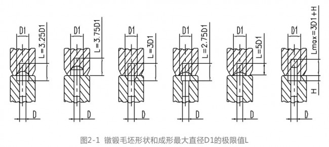
The reference value of the limit value of the free length L of the deformed portion of the blank when the two-step forward is used is the same as the reference shape of the upset forging and the maximum diameter D1 of the forming is shown in Fig. 2-1.
2.2 The use of a tapered punch with a cylindrical section (commonly known as the teat die) can improve the stability of the pretension:
Because the use of such a punch will increase the end clamping rigidity. Whether preformed or subsequently formed, the angle of the cone cavity has an effect on the stability of the blank.
If the cone angle β is small, the stability of the blank is improved, but the probability of instability in the subsequent process may increase. Therefore, the first station must be designed with the tapered taper with the best taper. If it does not meet the appropriate requirements, it will be in the cylinder direction. Annular folds are formed at the location of the cone transition.
When 2β≥20° and the cylinder and the cone are non-circular transitions, the improper pre-formation will form a dividing line when the final upsetting is performed, and even a round fold will be formed. When 2β = 12~15°, the upsetting of the tapered head will result in good metal flow.
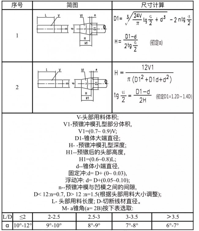
Refer to Table 2-1 for the calculation of the dimensions of the pre-thickening taper forming process.
Table 2-1 Dimensional calculation table for pre-crimping and taper forming process
A fixed conical punch is used when S ≤ 3.25, and a floating conical punch is used when 3.25 < S ≤ 6.5. The floating stroke calculation of the floating cone punch is preferably carried out by drawing: the upper and lower molds are closed for dynamic initial and final patterns, and the initial state of the wire is all entered into the cavity, and then the cavity is squeezed into the end of the cone. The measuring stroke is the floating stroke.
In order to ensure the stability and head forming quality of some rod-shaped parts during the second-order upsetting, the pre-upsetting shape recommended by National Machines Corporation is shown in Figure 2-2.
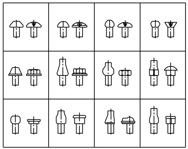
Figure 2-2 Double-clicking the best shape for upsetting during upsetting
The dimension design of the pre-thickening taper forming process is very important. It is difficult to achieve the vertical shape stability of the blank, and it is difficult to achieve the design of the best shape for the subsequent forming. Therefore, the design is only "nine-nine" and there is no "full". Only rely on "practice to know the truth."
Graphite Electrode,Rp Graphite Electrode,Regular Power Electrodes,Graphite Electrode With Nipples
Carbographite Industrial PTE.LTD , http://www.graphites.pl