- First, the initiation and expansion of the dimple crack
The dimple break consists of three stages, the initiation of cracks - the formation of microscopic holes, the extended aggregation of cracks and the final fracture, see Figure 3-12.
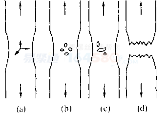 Figure 3-12 Schematic diagram of tensile fracture process(a) necking leads to three-direction stress (b) microscopic holes are formed in the central region of the neck;(c) The hole grows to form a serrated crack (see Figure 3-13a); (d) The final edge shear fracture (see Figure 3-13b)
When the material is subjected to tensile load, plastic deformation occurs when the stress exceeds the yield strength of the material, resulting in necking to form a three-direction stress state. The central axial stress increases with the progress of necking. Under the action of three-direction stress, the micropores are separated at the interface between the precipitate phase, the inclusions and the metal, or the inclusions themselves are broken to form cracks, and the pores may be generated due to the displacement of the strong slip and slip, as shown in Fig. 3-12 (Fig. 3-12) a) (b). 3-14 shows that the Al-Li-Cu-Mg-Zr alloy is treated by 530 ° C for 30 minutes + 190 ° C for 10 hours, and the inclusions themselves are broken to form cracks. Fig. 3-15(a) shows the quenching state of Al-Li-Cu-Mg-Zr530 °C in 30 minutes, the crack is initiated at the strong slip, and (b) is expanded.
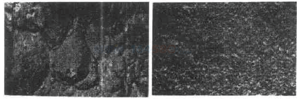
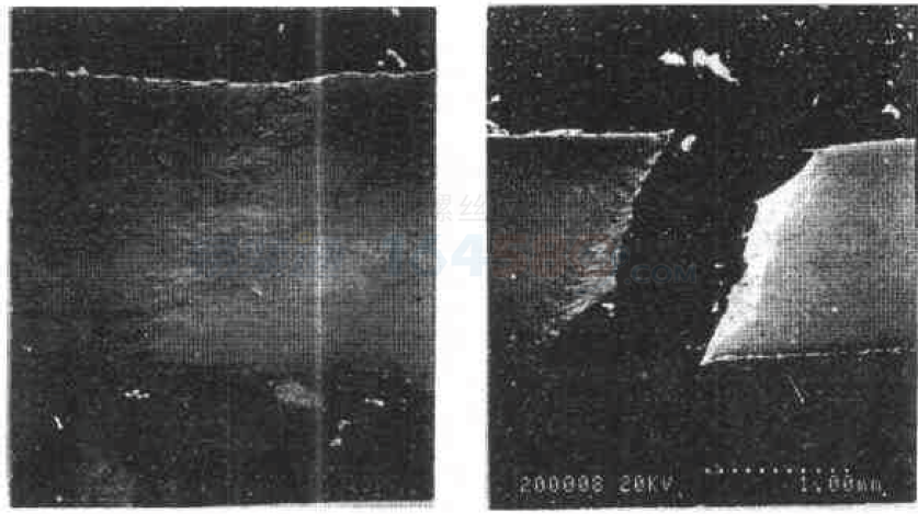 (a) (b)Figure 3-13 Photograph of tensile fracture process
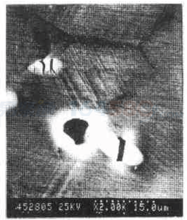 Figure 3-14 The inclusion itself breaks and forms a crack
Inclusions or second phase particles play an important role in the fracture of the dimple. The larger the particle point, the higher the probability of crack initiation. The size of the dimple is usually larger than the distance between the particles, indicating that not all the particles are active at the time of the fracture, there is a critical mass size problem, and the critical mass size decreases with decreasing temperature. When fracture occurs at lower temperatures, a decrease in dimple size indicates that a larger proportion of the particles have cracked. A certain person's small particle only works at a certain temperature. For example, 18% Ni maraging steel is quenched at 475 ° C for 4 hours after quenching, and stretched at -196 ° C to obtain a coarse dimple fracture. Analysis showed that the precipitation phase was too small at the beginning of aging and no dimples were formed. Only those undissolved coarse particles form micropits, see Figure 3-16(a). If tempered at 475 ° C for 600 hours, a fracture with a very small dimple is obtained at the same stretching temperature, Figure 3-16 (b).
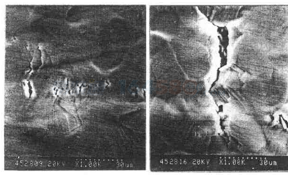 (a) (b)Figure 3-15 Cracks sprout at the strong slip(a) Cracks sprout at strong slips; (b) Cracks expand at strong slips
Studies have shown whether cracks can be generated at the particle point, and the degree of density of the particle is related to the matrix. The combination of fastening is not easy to initiate cracking, and conversely, it is easy to initiate cracking.
After the micropores are formed, there are two types of expansion methods: internal necking expansion and shear expansion.
The internal necking expansion is the size of the particle, the market is uniform, and the dimples are cracked at multiple locations. Later, as the deformation increases, the microporous walls become thinner and are connected by tearing.Shear expansion is when there are more inclusions in the material and there are fine precipitates, and the micropores may be connected by shearing. Internal necking and shear expansion may occur simultaneously on the same dimple fracture.
 (a) (b)Figure 3-16 18% Ni maraging steel - 196 ° C tensile fracture
Second, the microscopic mechanism of crack formation
D.Broek established a dimple initiation and expansion model based on experimental results and dislocation theory, as shown in Figure 3-17.In the material, a dislocation loop is accumulated around the inclusions or the second phase particles, as shown in Fig. 3-17(a). On the one hand, the dislocation ring is repelled by the second phase particles or inclusions, and on the other hand is pushed by the dislocation packing stress to the second phase particles or inclusions. They are in a dry balance when there is no external force, see Figure 3-17(b). When subjected to an external force, the balance is destroyed and the dislocation loop is pushed toward the second phase particles. After one or a pair of dislocation loops are pushed onto the particle-substrate interface, the interface will be separated along the AB plane in Figure 3-17(c) to form micropores. Due to the formation of micropores, the repulsive force of the latter dislocations is reduced. On the other hand, the source of dislocations behind the in-situ fault ring is reactivated, creating a new dislocation loop that is constantly pushed toward the micropore, causing the micropore to expand rapidly, see Figure 3-17(d)(e). Since dislocations can travel along different slip planes to the particle boundaries, the micropores can be formed by dislocations from several slip planes, Figure 3-17(f). Or dislocations on other slip surfaces move toward the microhole to grow it, Figure 3-17(g).
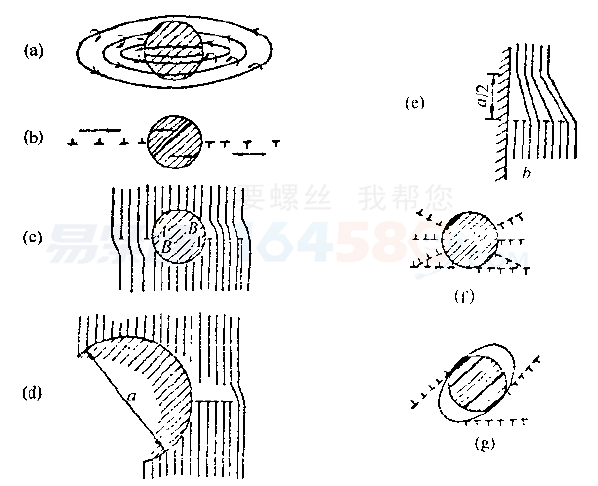 Figure 3-17 Formation and growth model of the dimple(a) dislocation loops accumulated around the particles; (b) stress balance;(c) under the action of shear stress, the dislocation loop moves toward the boundary to form micropores; (d) (e) micropore expansion(f) forming micropores by a few slips and opening up dislocations; (g) growing micropores
Figure 3-18 is a micropore growth model based on the D.Broek theory. This model can simultaneously explain the formation of equiaxed dimples or parabolic dimples under shear stress. In addition, it can also explain the case where the inclusions or the second phase particles are broken under the shear stress to form a dimple.
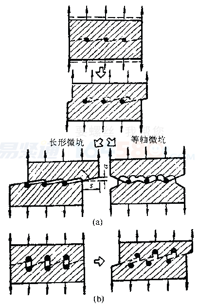 Figure 3-18 Growth process of the dimple(a) formation of equiaxed dimples, parabolic dimples;(b) Broken by inclusions to form dimples
Graphite Part,Other Graphite Parts,High Purity Graphite Part,High Strength Graphite Part
Henan Carbons New Material Technology Co., Ltd. , https://www.hncarbons.com