Such an arbitrary surface can naturally be dealt with, and it is also a perfectly reasonable practice, but when processing a regular surface such as a spherical surface, there are some problems in the process. Due to the limitation of the underlying mathematical model of the CAD/CAM software construction surface, and because the CAD/CAM software limits the approximation principle of the surface generation tool path, the software cannot judge this intelligently when taking the actual full circle or arc. In fact, it is a "true circle or arc". The generated program is not a G02/G03 command, but a "circle" formed by G01 point-by-point approximation - it can be imagined to use a positive N-edge to approximate a circle, but only This N is very big. If the full circle or arc is seated in the G18 or G19 plane, there is no chance to generate the G02/G03 command. This also explains why the programs generated by CAD/CAM software are "born". When the program is executed, the numerical control system between each adjacent approximation point must perform linear interpolation operation. The computer workload of the system is huge, which is reflected on the machine tool, which is inevitably characterized by slow motion and incoherence. As shown in the figure below, the surface looks like the same hemisphere, but in CAD there are actually many different modeling methods. Figure 1 shows a 1/4 arc in the ZX plane as the bus, with the Z axis. The hemispherical surface obtained by rotating 360? for the axis; Fig. 2 is a hemispherical surface obtained by rotating a section of 1/2 arc in the XY plane as a busbar and rotating the axis by 180. Even with solid shapes (such as Pro/E, SolidWorks, etc.), there are similar differences in the mathematical mechanics of the underlying sketch construction.
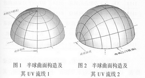
It can be seen that the UV streamlines that constitute the hemispherical curvature are completely different in both cases, and various CAD/CAM softwares must have differences when generating the hemispherical surface finishing toolpath. Simply put, even the Cima-tron software, which is widely regarded as one of the most outstanding CNC programming software in the industry, is only in rare cases (as in Figure 1 below) and in the Surmill way (similar to that in Mastercam). The surface streamline processing), Cimatron software can judge that this is actually a "true round", the generated tool path itself is the "true round", the post-processing program is mainly from G02/G03 Instruction composition. If you use srfpkt, 3D_step and other other way, it is definitely the result of approximating with G01.
Let's take another very simple example. For example, using a milling cutter to machine the inner hole in a spiral way, the macro program is not only very short, but the line 20 is not available! Moreover, the feed speed f=2000mm/min can maintain a very uniform and fast spiral motion when the machine is actually running. In Cimatron software, even if helicprf is used in the external user function user, a similar tool path can be generated. However, the tool path is approximated by G01 step by step according to the given error value (usually 0.01). The number of program bytes is basically two orders of magnitude larger than the macro program, and even if the entire program is stored in the controller of the machine tool. The speed of the actual operation of the machine tool is basically not going up. It is not obvious below F600. If the F value hits F1200 or so, you can see that the machine tool is obviously "shaking".
For high-speed machine tools that support NURBS curve interpolation in CNC systems, if you use CAD/CAM software with high-speed machining functions to coordinate programming, there is certainly not much problem; but for most CNC systems, it is always a problem. .
In fact, CAD/CAM software vendors are not likely to be unaware of this problem. In fact, various CAD/CAM software also provide some other ways to improve this, but they are not fundamentally solving congenital problems, but Make a fuss about the "After the Day" link. As we all know, the principle of CAD/CAM software programming is to first generate a tool point file (ie, toolpath track) containing only purely geometric meaning. This process is often background and opaque to the user, such as Pro/E. The CL file (Cutter Location File), the UG CLF file, the Mastercam NCI file, the Cimatron APT file, etc., and then go through a very important part of the post-processing, in order to generate a true certificate program.
What CAD/CAM software can do is to make a fuss about post-processing without changing the tool position file (that is, using the G01 straight line approaching the path of the tool path). For example, in the post processing of Mastercam software, the user is allowed to set the minimum radius value and the maximum radius value to generate the G02/G03 command. In fact, G02/G03 is used to approximate (accurately, it should be "fit") adjacent. A number of straight line segments are used to reduce the program bytes and improve the actual running speed of the machine.
Previous Next
Product Name: Ferric hydroxide

Chemical formula: Fe (OH) 3
CAS accession number: 1309-33-7
Melting point: 757 C (25kpa)
Appearance: brown or reddish brown powder or dark brown floc
Nickname: three Ferric Hydroxide
Molecular weight: 106.867
Density: 3.4~3.9g/cm fand
Application: net water and arsenic antidote.
English Name: TRIHYDROXIDE IRON
EINECS accession number: 243-746-4
Water soluble: difficult to dissolve in water
Safety Description: should not contact with the human body surface
Ferric hydroxide
Ferric Hydroxide,Six Water Chloride,Chloride Six Water,Six Water Compound
Xi'An Lanzhiguang Fine Material CO.Ltd , http://www.lanzhiguangchem.com